Famicom HVC-001 dead on the bench: blown fuse and a tired 7805
Symptom No RF carrier on channel 1 or 2, no audio hiss, case stays cold while the HVC-002 adapter gets warm.
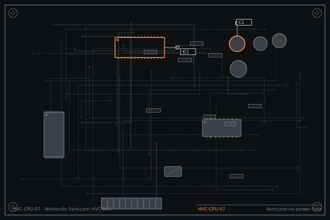
A Famicom that produces nothing at all is usually the easiest board on the bench to clear. Two parts sit between the barrel jack and the CPU, and both are cheap. This dossier walks the DC path from the adapter tip to the 5 V rail and shows what a healthy reading looks like at each stop.
What the owner reports
Power LED: none, because the HVC-001 has no LED. Instead you get a completely blank picture on the TV, no white noise behind the RF carrier, and no audible hum when the volume is turned up. The console shell never warms up even after ten minutes, while the HVC-002 brick is noticeably warm. That combination is the tell: current is leaving the adapter and never reaching the board.
Rule out the obvious first. The HVC-002 puts out 10 V DC at 850 mA through a 5.5 x 2.1 mm centre-negative barrel. A modern 9 V centre-positive supply will not work and can look exactly like a dead console. Check polarity on the adapter and on the jack before opening anything.
Tracing the DC path
Open the shell with a JIS #1 driver, not a Phillips. The six case screws on a Famicom are JIS and a Phillips driver will cam out and scar the heads. With the top shell off, the RF modulator can sits in the rear right corner. The fuse is inside that can, soldered to the modulator board, and it is the first thing in the path after the jack.
Work in this order and write each number down. A single skipped measurement turns a ten-minute fix into an afternoon of guessing.
- Unplug the adapter and measure resistance across the barrel jack pins. A short here means the jack itself has failed, not the fuse.
- Power up and measure DC at the jack pins on the board. Expect 10.0 to 11.5 V unloaded. Anything under 7 V points at the adapter, not the console.
- Follow the trace to the RF modulator can. Measure both ends of the fuse F1 in-circuit. A good fuse reads under 1 ohm; a blown one reads open or several megohms.
- If F1 is open, measure the input pin of the 7805 regulator (IC1) to ground for a short before fitting a new fuse. A shorted 7805 will blow the replacement instantly.
- With a known-good fuse, power up and measure the 7805 output. Target is 5.00 V plus or minus 0.25 V. Below 4.75 V under load means the regulator has failed.
Replacing the fuse and the regulator
The original part is a 1 A pico fuse about 7 mm long. A 1 A slow-blow pico fuse is the correct substitute; do not fit a 2 A part to stop it blowing again, because the fuse is protecting the 7805 and the 5 V rail behind it. Solder it standing slightly off the board so the next person can read the rating.
If the 7805 is dead, replace it with a 7805 in a TO-220 package and bolt it to the existing tab. A 100 nF ceramic from input to ground and a 10 µF electrolytic on the output keep the rail quiet and stop the regulator oscillating, which is what kills these parts in the first place.
- Desolder the old fuse with a 350 °C iron and a solder pump. Clean the pads with braid.
- Fit a 1 A pico fuse. Check continuity across it before applying power.
- If the 7805 is being replaced, add a small aluminium heatsink. The stock tab runs near 60 °C in a closed shell.
- Power up with no cartridge. The 5 V rail should read 5.00 V plus or minus 0.25 V and the board should draw roughly 350 to 450 mA at idle.
- Reassemble and test with a known-good cartridge before closing the shell.
Fault tree branches
where this symptom also leadsIf: Fuse is intact and the 5 V rail reads correctly, but the picture is still blank
Move to the video path: check the RF modulator output and the channel select switch before suspecting the PPU.
NES front loader blinking: 72-pin connector and the 10NES reset loopIf: The 5 V rail reads 5 V unloaded but collapses to 3 V with a cartridge fitted
The 7805 is current-limiting. Look for a shorted capacitor on the 5 V rail.
If: The rail reads correct but there is a continuous 50 or 60 Hz hum in the audio
Suspect the main filter capacitor rather than the regulator.